FAQ
See PROFIBUS FAQ below
PROFINET FAQ to be added shortly –
ProfiTrace Licening FAQ link here
PROFIBUS : PROFIBUS is an internationally recognised, open standard, for high speed, serial communications, as very widely used for linking industrial PLC – Programmable Logic Control computers to sensors and actuators in intelligent, distributed, process and factory automation control and monitoring systems.
The PROFIBUS Standard for bus wiring and associated communication protocol was first release more than 30 years ago and is still in very widespread use throughout the world, with many millions of PROFIBUS devices so linked and new systems still being built. It has succeeded for so long due to it’s comparative simplicity, versatility, security and its excellent reliability and resilience, provided that the strict installation guidelines (‘rules’) are followed in the associated connecting cable design and build, and that only PROFIBUS Certified devices, materials and procedures are used for such construction.

PLC : Process Logic Controller – dedicated, special purpose industrial computer. These are programmed to run cyclically, checking for activation of any user control selection buttons and switches, then checking current plant measurement inputs, before returning appropriate control output signals to plant condition activators, such as motors, valves, divertors etc. and any associated control panel status indicators to achieve the required plant operational purpose/function.
PROFIBUS DP / PROFIBUS PA : There are two different PROFIBUS signalling standards, with the more frequently seen PROFIBUS DP (for Distributed Periphery) employing high speed RS-485 standard and the much slower PROFIBUS PA (for Process Automation) employing Manchester Bus Encoding for sending serial data over single pair of power cables to typically outdoor (or other IP65+ rated) slave devices. Both PROFIBUS DP and PROFIBUS PA schemes use identical communications message formats and protocol, albeit usually at very different signalling data speeds.
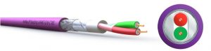
Cable Types : There are many different PROFIBUS DP and PROFIBUS PA cable types, spanning make-up, sheath arrangements, sheath material options, sheath colours, screen/shield details, internal conductor materials (solid, or stranded for vibration/ motion tolerance), armoured, food, trailing etc. All include two signal conductors, coloured Red and Green, with overall wrap-round foil and stranded braid shielding layer, beneath external sheath.
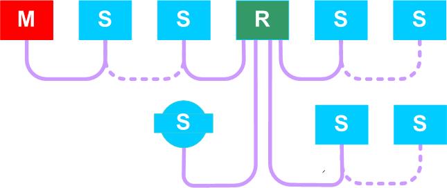
Cable connection arrangements : PROFIBUS cables may be arranged as point-to-point connections between pairs of devices or, more frequently, in multi-drop arrays connecting more than 2 slave devices to a PLC/Master.
Redundancy : When a control system needs enhanced reliability, or any particular link in a network is seen as vulnerable to potential damage or other weakness, control engineers may want to add an alternative, parallel connection – this is called a redundant link, which should automatically come into play if the first link should fail. For some systems alternative redundant PLC/Masters are used, followed by two totally separate connection paths to all slave devices. Each of these slaves then needs to be connected via two separate repeater channels, pre-set for redundant operation over those channels.
Optical connection arrangements : PROFIBUS signals may be transferred using fibre optic links (or wireless), for potentially long distances and to avoid electrical grounding problems. Fibre optic links use either single mode (SM) or multimode (MM) fibre signalling and require optical link modules (OLMs) to transition signals between copper and fibre cables, and fibre back to copper. Both linear and ring connection options are often used, with ring arrangements used for enhanced connection resiliance/reliability. Optical infra-red, line of sight connections, are also used within factories and warehouses for linking to/from rail mounted moving platforms.
OLM : This is the commonly used abbreviation for Optical Link Module, which is described in the previous paragraph, and are used for connecting copper PROFIBUS segments to and from optical fibre cables for message transfers.
Cable Plugs : Copper PROFIBUS cables connect a master station to slave, or slaves, frequently using 9-pin special PROFIBUS plugs, most of which include built-in terminator resistor networks with associated activation switches. These plugs usually allow for both incoming and outgoing PROFIBUS cables, with clear identification of each port direction shown on the outside of the plug case. Rounds M12 from connectors are also used.
Care must be taken when constructing multi-drop PROFIBUS cable arrays to ensure that the correct input and output ports are used when attaching cables to each device, as the terminator switch in each 9-pin PROFIBUS plug will disconnect signals from the outgoing cable when set (as may be needed during commissioning and fault-finding, for example). These 9-pin PROFIBUS plugs may also be fitted with rear PG test sockets to allow connection of PROFIBUS signal analysers, such as ProfiTrace, for testing. 9-pin plug formats vary considerably, with 0/180 degree, 45 degree and 90 degree versions available to cater for alternative cable arrival angles, and with different internal signal conductor connection methods, as needed to cater for solid core (most common) or stranded flexible wires.
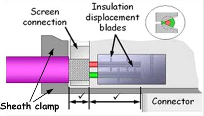
Fast Connect (FC – Insulation Displacement) now preferred for solid core cables to minimise cable preparation work and fitting time, with screw connection or sprung ‘cage-clamp’ arrangements offered for stranded wires.
Segment : A PROFIBUS Segment is the section of copper cable linking from 2 up to 32 PROFIBUS devices. Each such segment must have a resistive terminator set at each end to limit signal reflections back down the cable, which might otherwise stop successful message transfers. The maximum length of each segment depends on the communications speed (bit rate) used, with, for example, 200 metres as the recommended length limit at 1.5 Mbits/sec bit speed.

Repeater : A PROFIBUS Repeater is an electronic module which is used to extend an existing segment or network, to increase its permitted length and/or allow connection of more slaves, but with electrical isolation provided between the incoming and outgoing segments. PROFIBUS message data transfers seamlessly in either direction through repeaters, which are, in many cases, not visible to a controlling PLC or any connected bus analyser. Historically the first repeaters linked single input with single output segments, but more recently the scope has been extended by some suppliers to cater for up to 5 outgoing segments, with some composite repeaters now available combining both copper and fibre optic data connections.
Terminator : PROFIBUS terminators consist of simple resistor arrays which connects between the red and green signal conductors at each end of every copper PROFIBUS cable segment. When also connected to a low voltage power source, they stop high speed PROFIBUS signals from being reflected back down the cable, so preventing signal interference and potential message corruptions.
It is important that only 2 such terminators are set for each segment and that these remain permanently powered to operate successfully. Terminator networks are included in most 9-pin PROFIBUS plugs, with activation by in-built slide switch. Power for these terminator networks is provided by the slave or master device into which that plug is fitted : if, for any reason, the plug is removed from the power source, the associated termination network effectiveness will be very much reduced and may prevent continued operation of that complete network. In order to address this risk, special Active Terminator Modules are offered, some now with dual power input sockets for power resilience. These are widely used, particularly within the UK Water Industry.
When round M12 connectors are used for linking PROFIBUS signals, a special M12 Terminator Plug is used at the last device of a segment, once again taking power from that device to make the terminator network function effectively. When a device is hard wired onto the network cables, other arrangements are usually offered within the device housing to cater for end of segment location, or they must be followed on that segment by a separately powered Active Terminator.
PROFIBUS Speed : PROFIBUS signals can be sent at very different signalling speeds, from 9.6 kbit/sec, up to 12 Mbits/sec, but remain fixed for any one network, with most commonly seen speed at 1.5 Mbits/second for many control networks.
Each PROFIBUS network is driven by a PROFIBUS Master which controls and organises communications over that network, addressing all of the network slaves each cycle, in strict numerical order of their individual network addresses, sending new control commands (if applicable) and/or taking new measurements (where applicable) from each in turn. The total cycle time is therefore the time taken for addressing and taking replies from all of the individual devices in that network, which will in turn depend on the total number of devices addressed, the amount of data to/from each and the data speed : more devices + more data to/from each = slower cycle time.
Both outgoing communication messages to slaves from a Master and reply signals from these travel over a single pair of wires in a time-division-multiplexing arrangement. This needs clear (quiet) separation times between outgoing and incoming signals.
Note that the associated controlling PLC cycle time may be very different from that of the network communication cycle time, as each can operate independently from the other, communicating typically using shared memory data tables.
Master : Low level details of PROFIBUS network communications are controlled and driven by a network master, which is usually part of the overall controlling PLC computer unit. The master sets the data bit rate, sending regular messages out to each slave device in turn, allowing a short time for return of reply message from each, until all required devices have been addressed, at which point the communications cycle is re-started. A major strength of the PROFIBUS communication system is that it can cope with occasional short term interruption or corruption of communications to and from individual devices, whether due to electrical interference or message corruption for other reason, with the master often allowing up to 4 or 5 attempts at securing successful reply from any one device, before reporting loss of that device to the PLC.
Slave : PROFIBUS communication networks link masters to slaves. Generally a single master in each network controls the communication, as directed by a PLC, passing information requests to each of the connected outstation slaves, one at a time, in strict numerical order. Individual slave devices can perform plant value measurement functions, handle output and activation of control commands, or sometimes combinations of both. Each slave in a PROFIBUS network is assigned a unique network address in the range 0 to 126, with lower addresses generally reserved for masters or test instrumentation, and address 126 reserved for a new slave awaiting software set re-addressing to a different value.
Device Address : see Slave description above.
GSD File : Each individual slave type is assigned a unique 16 bit identifier code (ID) when first developed and registered with the PROFIBUS International organisation. This ID number is then used, generally with some abbreviation of the associated manufacturer name, to label a short text file which describes how the associated device operates and the meaning of any associated error messages which it might return during operational or set-up activity. This file is called a GSD file for that particular slave type, with the associated file name usually shown with a .gsd file type code added. Occasionally these file type codes can vary slightly with, for example, .gse sometimes used for English GSD language files. GSD files are used by PLC computers, when each new network is first set-up to allow the new control program to recognised and know how to communicate with and operate each particular slave type. During operational testing, they are used to give further information about each connected device, when requested (in a Class 2 Scan) to return their individual ID codes.
Cable Tester : Cable testing can mean many things, but for PROFIBUS, basic connection cable testing generally means verifying the correct termination of cables onto each, usually 9-pin, PROFIBUS plug, fitted at each end of a single length of cable, or daisy chained array, to confirm that the red and green signal cables are correctly fixed into the associated contacts at each end of the cable, without crossover or short circuit to each other or the cable screen/shield. Further testing for insulation resistance and/or connection quality may also be of interest, but are mostly undertaken using different, more general purpose electrical test instruments.
PROFIBUS Analyser : For successful PROFIBUS communications over a network, we need to have essentially square wave signal waveforms moving back and forth over the linking cables, to allow transfer of valid plant measurement values to the central PLC, then return of associated plant control signal messages, covering all required and connected devices.
PROFIBUS analysers therefore mostly allow inspection and measurement of the essential network waveform quality, showing waveform shapes and voltages, and then look into and report on the various message details, particularly checking for and highlighting any associated alarms or signs of possible weakness. Reports, including comprehensive information about a new network, logged at completion of initial plant commissioning and handover, provide a valuable long term record to confirm then successful and reliable plant operation, but also serve as a very useful benchmark reference against which later performance and operation can be compared.
Diagnostics : Diagnostic features are sometimes included within control system and other electronic devices to help highlight and report failures with that device, or input signals to it. Procentec have recently added switch selectable diagnostic features to many of their ProfiHub range of repeaters : these allow that device to start operating as a network slave, then reporting details of device settings and any detected signal failures over the control network to the PLC/Master and/or other connected units.
HMI : This is generally taken to indicate Human to Machine Interface/Indicator (panel). At one time generally a dedicated panel with control setting switches, sometime showing plant status indications, data values and alarms, but now often implemented in the form of electronic touch screen computer panels.
SCADA : Supervisory Control And Data Acquisition systems are generally autonomous computer systems, found in automation plant control rooms, and used to monitor and record operations of connected control systems, typically for monitoring and recording plant status and throughput.